Appearance
ROS2基础教程 - 13 URDF机器人建模
URDF(Unified Robot Description Format)是 ROS 2 中用于描述机器人模型的一种 XML 格式文件,它提供了一种标准化的方式来表示机器人的结构、关节、链接以及各种属性。
我们为什么要进行机器人建模呢?
- 在仿真环境中,我们可以定义机器人模型,来模拟真实的机器人进行开发(仿真环境后面再介绍)。
- 通过定义机器人模型,可以建立机器人各个部件或传感器的关系,实现 TF 坐标系的转换。
URDF 文件就是一个 XML 文件,其中核心组件包括:
- Link(链接):表示机器人的一个部分,定义了其几何形状、质量、惯性等,例如用来定义底盘、轮子、摄像头。
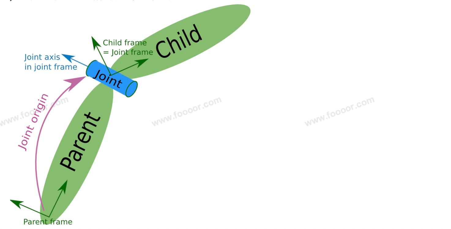
- Joint(关节):连接两个链接的方式,定义了它们之间的关系及运动模式(如固定、旋转、滑动)。
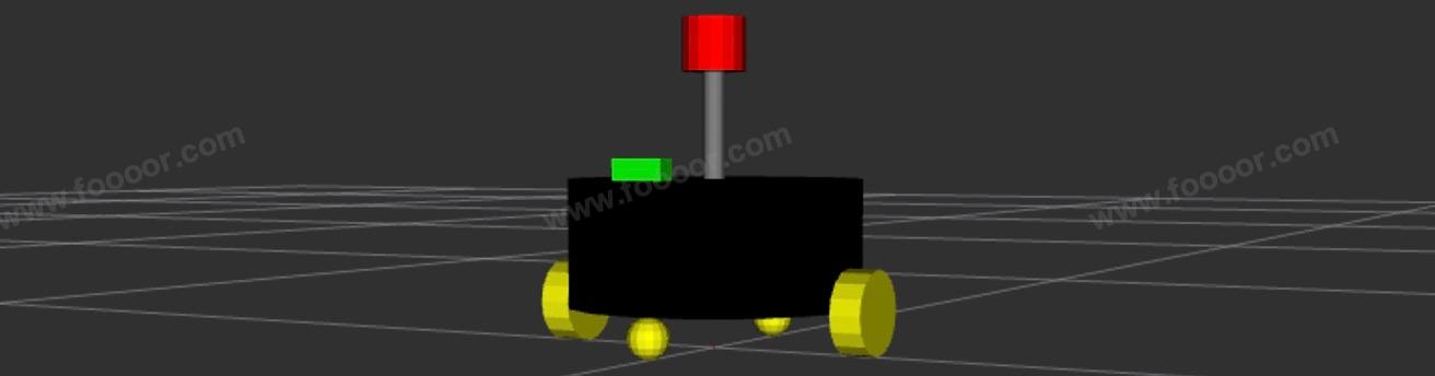
下面就来介绍如何使用 URDF 来定义一个机器人模型,最终显示如下:
13.1 URDF的使用
1 新建功能包
shell
ros2 pkg create --build-type ament_python robot_model2 创建URDF模型
在 功能包/urdf 目录下(没有就创建),创建一个 robot.urdf 文件(名称自定义),内容如下:
首先从机器人的身体开始定义,先不添加轮子。
xml
<?xml version="1.0" encoding="utf-8"?>

<robot name="robot">

    <link name="base_footprint">
        <!-- visual描述外观 -->
        <visual>
            <!-- geometry 设置连杆的形状 -->
            <geometry>
                <!-- sphere球体 -->
                <sphere radius="0.001" />
            </geometry>
        </visual>
    </link>

  	<link name="base_link">
      <visual>
        <geometry>
          <cylinder length="0.12" radius="0.14"/>
        </geometry>
        <origin rpy="0 0 0" xyz="0 0 0"/>

        <!-- metrial 设置材料属性 -->
        <material name="black_color">
          <color rgba="0 0 0 1"/>
        </material>
      </visual>
    </link>

    <joint name="base_link2base_footprint" type="fixed">
      <parent link="base_footprint"/>
      <child link="base_link"/>
      <origin xyz="0 0 0.1"/>
    </joint>

</robot>
解释一下上面的定义:
首先使用
<robot>标签定义机器人,这里的name属性是自定义的,然后在<robot>标签中定义各个组件。在上面使用
<link>标签定义了两个组件,一个是base_link表示的是机器人的身体,这里还定义了一个base_footprint,为什么要定义base_footprint呢,因为如果使用base_link坐标系作为机器人的根坐标系,那么因为轮子和机器人身体体积的原因,那么base_link中心点肯定不在地面上,为了简化坐标转换,所以将添加了一个base_footprint节点,就相当于是机器人在地面上的投影,它位于机器人的底部或与地面齐平,而且将其体积设置为很小,看不见。这样与全局地图map和 里程计odm坐标系的转换会方便一些。所以一般情况下,创建机器人模型,都是添加一个base_footprint,在base_footprint节点上构建机器人模型。在
<link>标签中,使用<visual>标签描述外观,使用<geometry>标签定义形状。xml<!-- 形状 --> <geometry> <!-- 球体,半径--> <sphere radius="0.01" /> <!-- 长方体的长宽高 --> <!-- <box size="0.4 0.2 0.1" /> --> <!-- 圆柱,半径和长度 --> <!-- <cylinder radius="0.5" length="0.1" /> --> </geometry>使用
<joint>标签,定义各个组件如何连接的,指定父link和子link,并使用<origin>定义子link相对于父 link的偏移和旋转,joint在模型中是不显示的。在
<link>标签和<joint>标签中都有<origin>标签,可以定义偏移和旋转,<link>的<origin>改变的是<link>的坐标系相对于默认坐标系的姿态位置,例如部件内部的某个东西(比如“外壳”或“重心”)相对于这个部件的中心点的位姿。而<joint>的<origin>是改变<link>在父坐标系的位置,所以设置相对于父组件的位置和角度,通过<joint>中的<origin>来设置,设置偏移和旋转弧度(ROS中用到的单位都是米和弧度)。上面设置了<origin xyz="0 0 0.1"/>,也就是base_link基于base_footprint中心在 Z 轴偏移0.1,base_link高度的一般是0.06,所以base_link离地面高度是0.04米,用于后面安装轮子。<material>用来设置材料属性,上面通过<color>设置RGB值和透明度。<joint>标签中type有如下的值:
continuous : 允许绕指定轴的无限制旋转(如车轮)。
revolute : 允许绕指定轴的有限旋转运动,机械臂的肘部或肩部,不能无限旋转。
prismatic : 滑动关节,允许沿指定轴的线性运动。
fixed : 将两个链接固定在一起,不允许任何相对运动。
floating : 允许6个自由度的运动(3个旋转和3个平移),用于定义完全自由的运动,一般较少使用。
planar : 允许在一个平面内的两个平移和一个旋转运动。
3 创建launch文件
下面使用 rviz 将模型显示出来。
在 功能包/launch 目录下创建一个 robot_model_launch.py 文件,内容如下:
python
import os
from launch import LaunchDescription
from launch_ros.actions import Node
from launch_ros.substitutions import FindPackageShare
from ament_index_python.packages import get_package_share_directory

def generate_launch_description():
    package_name = 'robot_model'
    urdf_name = "robot_model.urdf"

    # 获取功能包路径
    pkg_share = FindPackageShare(package=package_name).find(package_name)
    urdf_model_path = os.path.join(pkg_share, f'urdf/{urdf_name}')

    robot_state_publisher = Node(
        package='robot_state_publisher',
        executable='robot_state_publisher',
        arguments=[urdf_model_path]
    )

    joint_state_publisher = Node(
        package='joint_state_publisher',
        executable='joint_state_publisher',
        name='joint_state_publisher',
        arguments=[urdf_model_path]
    )

    rviz_config_path = os.path.join(
        get_package_share_directory(package_name),
        'rviz',
        'model.rviz'
    )

    rviz = Node(
        package='rviz2',
        executable='rviz2',
        name='rviz2',
        #arguments=[   # 在第一次运行后,保存配置后,指定配置文件的路径
        #    '-d', rviz_config_path
        #],
        output='screen'
    )

    return LaunchDescription([
        robot_state_publisher,
        joint_state_publisher,
        rviz
    ])
上面启动了三个节点、 ros-humble-joint-state-publisher 、 ros-humble-robot-state-publisher 、rviz 。
首先需要安装一下 ros-humble-joint-state-publisher 和 ros-humble-robot-state-publisher
shell
sudo apt install ros-humble-joint-state-publisher   # 我这里是humble版本
sudo apt install ros-humble-robot-state-publisher
joint_state_publisher :负责发布机器人关节数据信息,通过
joint_states话题发布robot_state_publisher :负责发布机器人模型信息
robot_description,并将joint_states数据转换 TF 信息发布。rviz :负责数据可视化,可以显示机器人模型
4 配置launch文件(重要)
在 setup.py 中新增 launch 相关配置:
python
from setuptools import find_packages, setup
import os
from glob import glob

package_name = 'robot_model'

setup(
    # ...其他配置
    data_files=[
        # ...其他配置

        (os.path.join('share', package_name, 'launch'), glob(os.path.join('launch', '*_launch.py'))),
        (os.path.join('share', package_name, 'config'), glob(os.path.join('config','*.*'))),
        (os.path.join('share', package_name, 'rviz'), glob(os.path.join('rviz', '*.*'))),
        (os.path.join('share', package_name, 'urdf'), glob(os.path.join('urdf', '*.*'))),  # urdf
    ],
    # ...其他配置
)
上面新增了三行配置,主要作用是安装 launch、config、rviz、urdf 目录中的文件到编译的 install 目录中,这样在运行的时候,能找到这些目录下的文件。(否则运行launch文件找不到)
注意,后面使用了通配符进行了文件的匹配,你需要按照规则命令launch文件,我这里launch文件需要以 _launch.py 结尾。
5 构建项目
现在代码已经编写完成了,需要构建项目。
在工作空间下执行如下命令:
shell
colcon build构建完成,会在 install 目录下生成文件。
6 运行节点
首先执行 source 命令,在工作空间下执行:
shell
source install/local_setup.sh上面的命令是让 ROS 找到我们的功能包,已经在 HelloWorld 章节说过了。
启动 launch :
shell
ros2 launch robot_model robot_model_launch.py运行后,会打开 rviz,打开后,Global Options -> Fixed Frame 选择 base_footprint。
然后添加 RobotModel :

选择RobotModel后,Description Topic 选择 /robot_description ,就可以显示刚才 urdf 中定义的模型了。
为了看的清楚,可以不显示 TF。
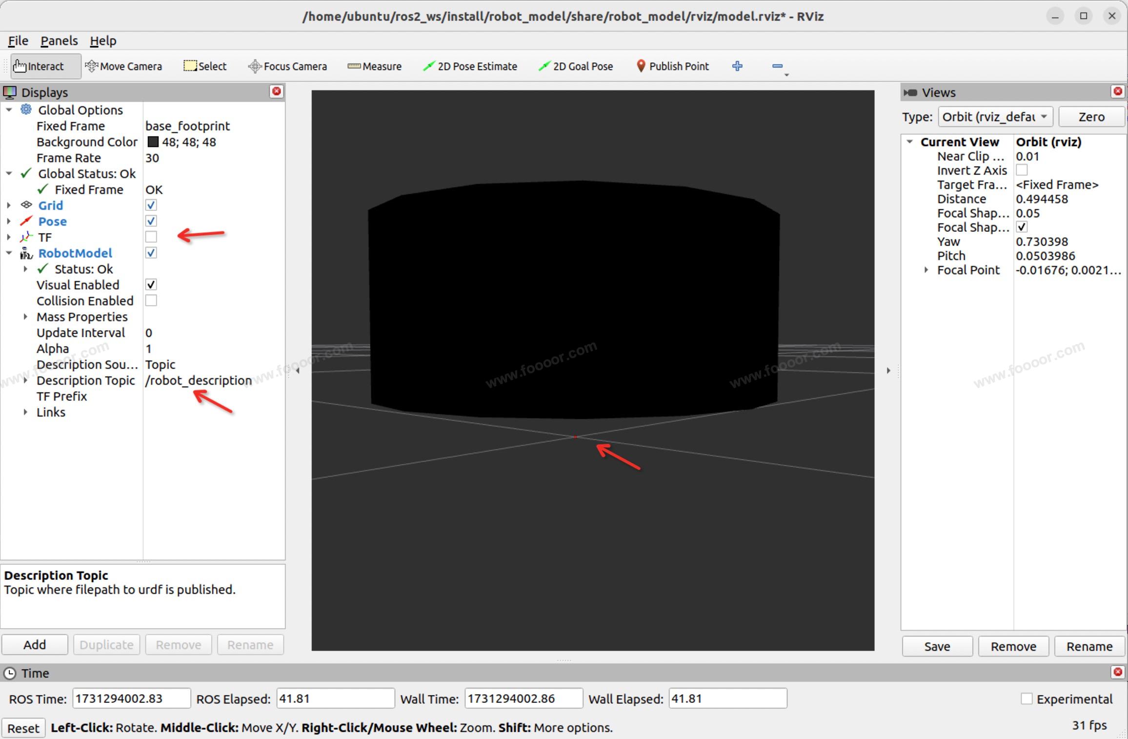
上面会显示 base_footprint 和 base_link。
每次打开 rviz,都需要手动添加 RobotModel,可以保存配置,然后在 launch 文件中启动 rviz 的时候,指定配置文件的路径。
13.2 继续完善模型
下面继续在上面的 urdf 的基础上,继续完善机器人模型,包括左右两个驱动轮、前后两个支撑轮,摄像头,雷达支架、雷达。
1 添加左右驱动轮
驱动轮是圆柱体,需要旋转90度(弧度),然后与 base_link 连接。
xml
<!-- 左轮 -->
<link name="left_wheel">
<visual>
<geometry>
<cylinder length="0.03" radius="0.04"/>
</geometry>
<origin rpy="0 0 0" xyz="0 0 0"/>
<material name="yellow_color">
<color rgba="1 1 0 1"/>
</material>
</visual>
</link>
<joint name="left_wheel2base_link" type="continuous">
<parent link="base_link"/>
<child link="left_wheel"/>
<origin xyz="0 -0.155 -0.06" rpy='1.57 0 0' />
</joint>
<!-- 右轮 -->
<link name="right_wheel">
<visual>
<geometry>
<cylinder length="0.03" radius="0.04"/>
</geometry>
<origin rpy="0 0 0" xyz="0 0 0"/>
<material name="yellow_color">
<color rgba="1 1 0 1"/>
</material>
</visual>
</link>
<joint name="right_wheel2base_link" type="continuous">
<parent link="base_link"/>
<child link="right_wheel"/>
<origin xyz="0 0.155 -0.06" rpy='-1.57 0 0' />
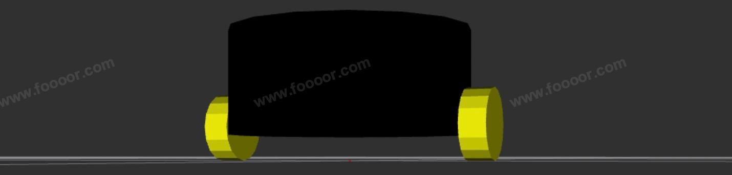
</joint>轮子是基于 base_link 中心点进行偏移的,base_link 的半径是 0.14 ,加上轮子的厚度的一半 0.015,所以在 Y 轴上平移 0.155;base_link 高度是 0.12,一半是 0.06,所以设置为 <origin xyz="0 0.155 -0.06" rpy='-1.57 0 0' /> ,-1.57 表示旋转90度。
添加完成,重新编译项目运行,显示效果:
2 添加前后支撑轮
前后支撑轮使用一个球体来代替。
轮子都定义成黄色,那么好多地方用到,那么可以在全局使用 <material> 标签用于定义材质和颜色,然后在 <visual> 标签中引用即可。
xml
<material name="yellow_color">
  <color rgba="1 1 0 1"/>
</material>

<!-- 前支撑轮,定义为一个圆球 -->
<link name="front_wheel">
  <visual>
    <geometry>
      <sphere radius="0.02"/>
    </geometry>
    <origin rpy="0 0 0" xyz="0 0 0"/>
    <material name="yellow_color" />
  </visual>
</link>
<joint name="front_wheel2base_link" type="continuous">
  <parent link="base_link"/>
  <child link="front_wheel"/>
  <origin xyz="0.12 0 -0.08"/>
</joint>

<!-- 前支撑轮,定义为一个圆球 -->
<link name="back_wheel">
  <visual>
    <geometry>
      <sphere radius="0.02"/>
    </geometry>
    <origin rpy="0 0 0" xyz="0 0 0"/>
    <material name="yellow_color" />
  </visual>
</link>
<joint name="back_wheel2base_link" type="continuous">
  <parent link="base_link"/>
  <child link="back_wheel"/>
  <origin xyz="-0.12 0 -0.08"/>
</joint>
base_link 离地 0.04,所以设置了支撑轮的半径为 0.02,并设置到 base_link 的前方和后方。因为是相对于 base_link 中心移动的,所以 Z 轴向下移动 base_link 高度的一半 加上 支撑轮的半径,也就是 0.08 。
添加完成,重新编译项目运行,显示效果:

3 添加雷达
我们先添加一个支架,然后将雷达安装在支架上。
所以雷达支架是相对于 base_link,雷达是相对于雷达支架进行定位。
xml
<!-- 雷达支架 -->
<link name="laser_bracket_link">
  <visual>
    <geometry>
      <cylinder length="0.1" radius="0.01"/>
    </geometry>
    <origin rpy="0 0 0" xyz="0 0 0"/>
    <material name="gray_color">
      <color rgba="0.5 0.5 0.5 1"/>
    </material>
  </visual>
</link>

<joint name="laser_bracket_link2base_link" type="fixed">
  <parent link="base_link"/>
  <child link="laser_bracket_link"/>
  <origin xyz="0 0 0.11"/>
</joint>

<!-- 雷达 -->
<link name="laser_link">
  <visual>
    <geometry>
      <cylinder length="0.05" radius="0.03"/>
    </geometry>
    <origin rpy="0 0 0" xyz="0 0 0"/>
    <material name="red_color">
      <color rgba="1 0 0 1"/>
    </material>
  </visual>
</link>

<joint name="laser_link2laser_bracket_link" type="fixed">
  <parent link="laser_bracket_link"/>
  <child link="laser_link"/>
  <origin xyz="0 0 0.075"/>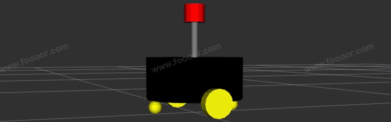
</joint>雷达基于支架向上移动,所以是支架高度的一半加上雷达高度的一半,0.05 + 0.025 = 0.075 。
添加完成,重新编译项目运行,显示效果:
4 添加摄像头
在底盘上方的前面,添加一个摄像头,使用一个长方体表示。
xml
<!-- 摄像头 -->
<link name="camera_link">
  <visual>
    <geometry>
      <box size="0.02 0.05 0.02"/>
    </geometry>
    <origin rpy="0 0 0" xyz="0 0 0"/>
    <material name="green_color">
      <color rgba="0 1 0 1"/>
    </material>
  </visual>
</link>

<joint name="camera_link2base_link" type="fixed">
  <parent link="base_link"/>
  <child link="camera_link"/>
  <origin xyz="0.13 0 0.07"/>
</joint>
添加完成,重新编译项目运行,显示效果:
最终的 robot_model.urdf 内容如下:
xml
<?xml version="1.0" ?>
<robot name="robot">

  <material name="yellow_color">
    <color rgba="1 1 0 1"/>
  </material>

  <!-- base_footprint -->
  <link name="base_footprint">
    <visual>
      <geometry>
        <sphere radius="0.001"/>
      </geometry>
    </visual>
  </link>

  <!-- 底盘 -->
  <link name="base_link">
    <visual>
      <geometry>
        <cylinder length="0.12" radius="0.14"/>
      </geometry>
      <origin rpy="0 0 0" xyz="0 0 0"/>
      <material name="black_color">
        <color rgba="0 0 0 1"/>
      </material>
    </visual>
  </link>

  <joint name="base_link2base_footprint" type="fixed">
    <parent link="base_footprint"/>
    <child link="base_link"/>
    <origin xyz="0 0 0.1"/>
  </joint>

  <!-- 左轮 -->
  <link name="left_wheel">
    <visual>
      <geometry>
        <cylinder length="0.03" radius="0.04"/>
      </geometry>
      <origin rpy="0 0 0" xyz="0 0 0"/>

      <material name="yellow_color" />
    </visual>
  </link>
  <joint name="left_wheel2base_link" type="continuous">
    <parent link="base_link"/>
    <child link="left_wheel"/>
    <origin xyz="0 -0.155 -0.06" rpy='1.57 0 0' />
  </joint>

  <!-- 右轮 -->
  <link name="right_wheel">
    <visual>
      <geometry>
        <cylinder length="0.03" radius="0.04"/>
      </geometry>
      <origin rpy="0 0 0" xyz="0 0 0"/>
      <material name="yellow_color" />
    </visual>
  </link>
  <joint name="right_wheel2base_link" type="continuous">
    <parent link="base_link"/>
    <child link="right_wheel"/>
    <origin xyz="0 0.155 -0.06" rpy='-1.57 0 0' />
  </joint>

  <!-- 前支撑轮,定义为一个圆球 -->
  <link name="front_wheel">
    <visual>
      <geometry>
        <sphere radius="0.02"/>
      </geometry>
      <origin rpy="0 0 0" xyz="0 0 0"/>
      <material name="yellow_color" />
    </visual>
  </link>
  <joint name="front_wheel2base_link" type="continuous">
    <parent link="base_link"/>
    <child link="front_wheel"/>
    <origin xyz="0.12 0 -0.08"/>
  </joint>

  <!-- 前支撑轮,定义为一个圆球 -->
  <link name="back_wheel">
    <visual>
      <geometry>
        <sphere radius="0.02"/>
      </geometry>
      <origin rpy="0 0 0" xyz="0 0 0"/>
      <material name="yellow_color" />
    </visual>
  </link>
  <joint name="back_wheel2base_link" type="continuous">
    <parent link="base_link"/>
    <child link="back_wheel"/>
    <origin xyz="-0.12 0 -0.08"/>
  </joint>

  <!-- 雷达支架 -->
  <link name="laser_bracket_link">
    <visual>
      <geometry>
        <cylinder length="0.1" radius="0.01"/>
      </geometry>
      <origin rpy="0 0 0" xyz="0 0 0"/>
      <material name="gray_color">
        <color rgba="0.5 0.5 0.5 1"/>
      </material>
    </visual>
  </link>

  <joint name="laser_bracket_link2base_link" type="fixed">
    <parent link="base_link"/>
    <child link="laser_bracket_link"/>
    <origin xyz="0 0 0.11"/>
  </joint>

  <!-- 雷达 -->
  <link name="laser_link">
    <visual>
      <geometry>
        <cylinder length="0.05" radius="0.03"/>
      </geometry>
      <origin rpy="0 0 0" xyz="0 0 0"/>
      <material name="red_color">
        <color rgba="1 0 0 1"/>
      </material>
    </visual>
  </link>

  <joint name="laser_link2laser_bracket_link" type="fixed">
    <parent link="laser_bracket_link"/>
    <child link="laser_link"/>
    <origin xyz="0 0 0.075"/>
  </joint>

  <!-- 摄像头 -->
  <link name="camera_link">
    <visual>
      <geometry>
        <box size="0.02 0.05 0.02"/>
      </geometry>
      <origin rpy="0 0 0" xyz="0 0 0"/>
      <material name="green_color">
        <color rgba="0 1 0 1"/>
      </material>
    </visual>
  </link>

  <joint name="camera_link2base_link" type="fixed">
    <parent link="base_link"/>
    <child link="camera_link"/>
    <origin xyz="0.13 0 0.07"/>
  </joint>
</robot>